- >
- Modules
- >
- >
- Hysteresis Thresholding
Module: Hysteresis Thresholding ()
Binarization transforms a gray level image into a binary image. This method is used when the relevant information in the gray level image corresponds to specific gray level interval. In the binary image the pixels of interest are set to 1, and to 0 for all other pixels (the background).The Hysteresis Thresholding uses a hysteresis loop to provide a more connected threshold result.
Two gray level values
and
(Thresholds parameter) are specified. The output is given by:
- If
, the point is in the retained area and is preserved:
- If
, the point is in the rejected area:
- If
, the point is in the fuzzy area. The point is preserved if connected to a retained area (
), or is rejected if not (
).
The Figure 1 represents an example of 1-D function. Figure 2 shows the result of a lower bound threshold with value
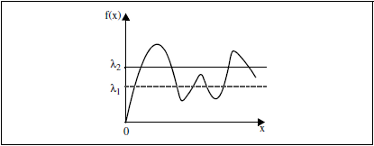
Figure 1: 1-D function
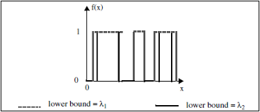
Figure 2: Low and high thresholds
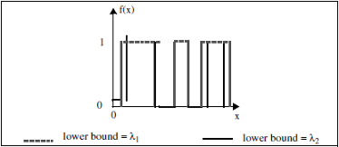
Figure 3: Hysteresis Thresholding, fuzzy area rejected Remarks:
This command can be used after an edge detection, which generates, as well as edges, a lot of noise. True edges have a higher chance to be connected to a retained area than pixels corresponding to noise.See also: Auto Segment 3 Phases, Auto Threshold high, Auto Threshold Low.
Input Image [required]
The image to be thresholded. Supported types include: Grayscale images (Uniform Scalar Field).
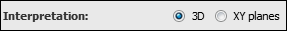
Interpretation
This port specifies whether the input will be interpreted as a 3D volume or a stack of 2D images for processing.
- "3D": the module configuration is set to 3D. The image will be processed as a whole in 3D.
- "XY planes": the module configuration is set to 2D. The image will be processed slice by slice.
Thresholds
This port defines the low and high threshold levels.Length
This port sets the maximum length allowed to connect a pixel in the fuzzy zone to a pixel in the safe zone. Length = 0 for reconnecting to stability.