
- >
- Modules
- >
- >
- Axis Connectivity
Module: Axis Connectivity ()
Given two parallel planes and a binary (or label) input image, Axis Connectivity generates a binary image containing all paths connecting the two planes.
By default, the two planes are a couple of parallel faces of the image's bounding box (the XY, XZ or YZ faces).
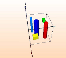
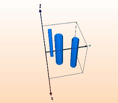
Figure 1: Example of input data, and the result of Axis Connectivity module with Z-axis orientation. If the input image is a binary image, it is first converted to a label image.
The module retains each region having a label present in both planes. If two disconnected regions with the same label are present on each face, they will be retained by the algorithm even if they don't cross the entire volume. To avoid this issue, the regions of the input image should be identified using a connected-component labeling algorithm, for example, by using the Labeling module. Note that if the input label field is binary, this preliminary labeling step is automatically applied by the Axis Connectivity module.
Data [required]
Data is the name of a label or a binary image.
Neighborhood
This port refers to the type of connectivity considered for processing adjacent voxels:
- 6: voxels with a common face are considered connected
- 18: voxels with at least one common edge are considered connected
- 26: voxels with at least one common vertex are considered connected
Orientation
The Orientation button defines the faces to be considered :
X axis : the YZ faces of the data bounding box;
Y axis : the XZ faces of the data bounding box;
Z axis : the XY faces of the data bounding box.
customPlanes <ix> <iy> <iz> <ex> <ey> <ez> <vx> <vy> <vz>
Defines two custom planes, using two points (P1 and P2) and their common normal N (cf. figure 2), and compute the result.
- ix, iy and iz are the coordinates of the first point P1;
- ex, ey and ez are the coordinates of the second point P2;
- vx, vy and vz are the coordinates of the normal vector N defining both planes.
The points coordinates are voxels' indices, and start by 1. The normal vector's coordinates can be float values.
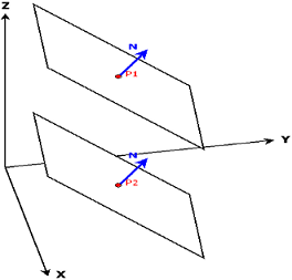
Figure 2: Defining two custom planes using two points and a normal vector

