Editor: Surface Editor ()
![]()
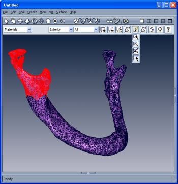
The surface editor allows you to modify a triangular surface in several ways, e.g., to remove or refine triangles, to flip edges or move points, or to set boundary ids for individual triangles. It also allows you to check a surface for intersecting triangles or for falsely oriented patches.To open a surface editor, in the Project View select the surface object to edit, then click on the Surface Editor button in the Properties Area. The surface editor places its GUI controls directly into the main 3D viewer window. This makes interactive surface editing very comfortable. In particular, the editor adds a Surface menu to the main menu bar, as well as a toolbar. The user interface of the editor is depicted in Figure 1. To close a surface editor, click again on the surface editor button in the Properties Area. Note that only one surface editor can be active at a time. Activating a second editor causes the first one to be closed.
To save your work, you can use the following entries of the File menu:
- Save: Saves the surface under the same file name as it has been saved under before. This option allows you to quickly save intermediate results during complex edit tasks.
- Save As...: Pops up the file dialog and saves the surface under a user-chosen file name and native file format.
- Export As...: Pops up the file dialog and export the surface under a user-chosen file name and file format.

Figure 1: User interface of the surface editor. The surface editor works in conjunction with a Surface View module. If such a module is not already connected to the surface, an instance of it will be created automatically when the editor is activated. However, most settings of the Surface View module can be controlled directly via menu entries of the editor itself. Therefore, there is no need to have the Surface View module permanently selected.
A basic concept of the surface editor are the notions of visible and highlighted triangles respectively. Highlighted triangles are drawn in red wireframe. Many tools operate not on the surface as a whole, but only on highlighted triangles. For example, if you want to refine parts of the surface, you'll first have to highlight the involved triangles before choosing Refine faces from the Surface/Edit menu. Besides the highlight buffer, there is another buffer determining which triangles will actually be drawn. This allows you to cut away parts of a complex surface. Highlighted triangles can be added to the visible buffer or removed from it, just as in an ordinary Surface View module. Note that hiding a triangle doesn't mean to delete it.
Triangles can be highlighted in a number of ways. On the one hand, there are interactive tools allowing you to select triangles using some kind of mouse interaction. For example, triangles can be picked individually or a contour can be drawn in the 3D viewer. Buttons representing the different mouse tools are listed in a toolbar. Clicking on a button causes the corresponding tool to be activated. On the other hand, triangles can be highlighted using automatic selectors. Selectors are listed in the leftmost combo box of the surface editor's selector toolbar. There are selectors for highlighting triangles depending on their inner and outer region, for highlighting triangles with a certain boundary id or belonging to certain patch, and many more.
In the following different elements of the surface editor will be described in detail, namely
- menu entries
- selectors including surface tests
- mouse tools for selecting triangles and editing the surface
- surface boundaries editor
The basic syntax of editor commands is
surfEdit <command> <optional-arguments>Remember this is only possible if surface editor is active.
Commands:
fillHoles <algorithm>
This command will fill a certain holes using algorithm which is listed on the <algorithm> index in the select box of the Fill hole... dialog which is accessible from Fill Hole... menu.fillAllHoles <algorithm>
This command will fill all holes with the appropriate algorithm which is listed on the <algorithm> index in the select box of the Fill hole... dialog which is accessible from Fill Hole... menu.flipEdge [<maxRatio> <maxCreaseAngle>]
The edge flips are performed in order to improve the aspect ratio of the involved triangles. An edge flip is only attempted if the aspect ratio of one of the two involved triangles is worse than a user-specified value, and the crease angle between them is below a user-defined threshold.
maxRatio if not specified has default value 20, and maxCreaseAngle if not specified has default value 30.fixIntersection
Automatic repair of intersecting triangles. The total number and the number of fixed intersections will be shown in the console window.fixDihedralAngle [<minAngle> <mode [0|1]>]
Automatic repair of small dihedral angles. There are two different repair modes: vertex smoothing (mode = 0), and a combination of edge flips and vertex shifts (mode = 1). You can define a lower bound for the dihedral angle. minAngle, if not specified, has default value 10, and mode if not specified has default value 1.fixTetraQuality [<maxRatio> <targetRatio>]
This tool provides an automatic repair of configurations which might induce large tetrahedron aspect ratios. You can specify an upper bound and an attempted value for the tetrahedron aspect ratio. maxRatio, if not specified, has default value 25, and targetRatio if not specified has default value 15.prepareTetraGen [<maxRatio> <targetRatio>]
This tool may be useful if you want to create a tetrahedral volume mesh from the surface. It combines the Flip edges, Fix small dihedral angles, and Fix tetra quality tools. You can specify a lower bound and an attempted value for the tetrahedron aspect ratio. maxRatio, if not specified, has default value 25, and targetRatio if not specified has default value 15.