- >
- Demos
- >
- >
- 3D Images Inspection

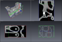
3D image data of an engine calibrated to detect 2 ranges: the Exterior and the Metal. It displays 3 orthogonal slices with an Ortho Views module. Then, a
Intensity Ranges Contours module is attached. (As the model has 2 ranges, the isolines displayed represents the interface between Exterior and Metal)

In this demo, the surface of an engine is shown on an underlying set of 3 orthogonal slices (displayed with an Ortho Views module). Note
that the Ortho Views module displays the cross section boundary of the surface relative to the 3 planes in red.

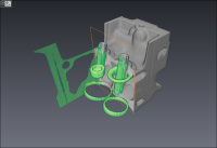
3D image data of an engine calibrated to detect 3 ranges: Exterior, Aluminium, Steel. It is displayed by 2 Volume Rendering modules with calibrated ranges corresponding respectively to Aluminium and Steel. Then an animation is performed with the Animation Director to show a cross section of the Aluminium part to reveal the steel parts of the engine.